There are 8 images on this page
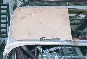
The wipers were not simple. Due to the widened body I required a different
layout. As I sit so low in the car it is important that the lower half of
the screen is wiped clear. A 180 degree sweep with the pivot of the wiper
low and as close to the screen would achieve this. I had originally wanted
to use a mechanical set up and had obtained a Ford Sierra wiper system but
this would be very difficult to fit and get working. So I decide to use a
Lucas rack and adapt the Sierra motor to it. This would allow me to easily
mount everything any where I wanted on the car, have a powerful 2 speed motor
with park and have any sweep I wanted (by altering the length of the crank
on the motor spindle) I had to build a new box which would adapt the rack
to the new motor. This was built from bolted together aluminium.
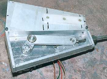
The internals of the motor control system were also modified to give me a
park.
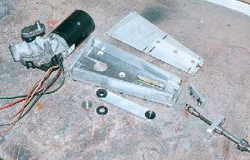
The only way to get 180
degrees of sweep was to build a new box. I used the Sierra motor as it is
faster than the Minor motor. The rack is from a Morris Minor.
-------------------------------------------------------------
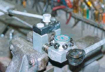
The insides of the new
box. To determine the length of the crank arm I fitted a wheel box into the
body and noted how much the rack moved when I moved the wiper through the
sweep I required.
------------------------------------------------------------
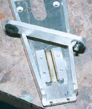

The white plastic slider
is from a Minor unit and I made two alloy blocks to hold it. The bolts in
each end locate the plastic.The arm is made from alloy with black plastic
bushes and a steel pin Loctited into position.
--------------------------------------------------------
The Sierra motor spindle
has a spline and key way on it. I had to use the Sierra arm which goes onto
this and weld it into my new crank arm. The only way I could make my new crank
with the required recess for the spline, holes and bosses was from a disc
then cut away the surplus. This was the only way I could hold the article
in the lathe.
------------------------------------------------------------
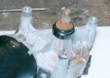
Marking holes in the
base of the new box to bolt onto the motor required a special technique. Sometimes
it is obvious what the spacing is between holes, it is 40mm, 1 1/2" etc.
But on the motor it was not obvoius, so I screw a pointed bolt into the hole.
Using the described method transfers the hole centres very acurately onto
the metal to be bolted to the motor.
---------------------------------------------------------
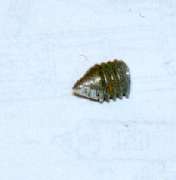
This is a close up of
the pointed screw. It is screwed into a hole so it just protrudes (see the
lower hole in the previous picture). The piece of metal requiring the hole
is `blued` and then placed into position. It marks the metal which is drilled.
The pointed screw is then put into another hole and the the metal (base of
the box in this case) is then bolted into position with the first hole drilled
and the procedure repeated.
------------------------------------------------------------
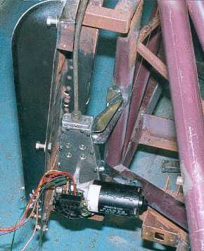
The new box and wiper
motor is mounted as low as possible on the chassis. This is an advantage of
using the Lucas rack system.
------------------------------------------------------------
The outer tubes require
flared ends to locate into wiper wheel boxes. Fortunately our flaring tool
had the correct dies for the tube. When installing the tube the runs are kept
as straight as possible and any bends have the largest radius possible.
------------------------------------------------------------